
The Cuproban System
Services & Systems
Fully automatic electrolytic seawater treatment — protecting pipelines, valves, heat exchangers, and condensers from marine biofouling and corrosion.
The Method
How Cuproban Works
Seawater Enters the System
Seawater is drawn into the vessel or installation through the sea chest or inlet pipework, carrying marine organisms, larvae, and corrosive elements.
Electrolytic Treatment
The Cuproban control panel passes a low electrical current through copper and aluminium anodes mounted at the point of entry. This electrolytic process dissolves minute quantities of copper and aluminium into the water. Where copper-nickel (CuNi) seawater pipework is fitted, soft iron anodes are used alongside copper anodes to prevent galvanic corrosion of the CuNi alloy. Iron anodes may also be placed inboard within a strainer where a sea chest installation is not possible.
Floc Formation & Distribution
The dissolved copper and aluminium form a fine "floc" that disperses throughout the entire seawater system — reaching every pipe, valve, heat exchanger, and condenser.
Continuous Protection
The copper floc inhibits marine growth (mollusca, algae, slime) from settling and breeding. The aluminium floc reduces corrosion and inhibits scale formation. The system operates automatically and continuously.
Protected Equipment
Cuproban protects:
Installation Options
The Right System for Every Application
Sea Chest Type Installation
For Ships & Vessels
Overview
The original Cuproban installation method developed by Barry Kirk in the early 1980s. Copper and aluminium anodes are fitted in the sea chest, treating seawater at the point of entry before it enters the ship's pipework. The sea chest configuration was established through early field installations on Sedco drilling rigs and subsequently adopted across merchant shipping, ferries, and offshore vessels worldwide.
Key Features
- Anodes fitted directly in sea chest
- Treats seawater at point of entry
- Designed around dry-docking schedule
- Copper, aluminium and soft iron anode configurations
- Soft iron anodes protect CuNi pipework against impingement corrosion
- Automatic control panel included
- Suitable for all vessel types
Inboard-Only Installation
For Platforms & Rigs
Overview
Developed by Barry Kirk to solve the specific challenge of offshore platforms and drilling rigs where dry-docking is not possible. Anodes are fitted inboard — inside the pipework or within a strainer — and can be changed at any time without taking the installation out of service. The use of soft iron anodes fitted inboard in a strainer to protect against impingement corrosion in CuNi seawater systems is original Cuproban development work, predating current commercial suppliers of equivalent solutions.
Key Features
- No dry-docking required
- Anodes changeable at any time without shutdown
- Separate controllers for each pump room
- Soft iron anodes fitted inboard in strainer
- Protects CuNi pipework against impingement corrosion
- Proven on Sedco semisubmersible and jack-up rigs from 1981
- Full remote monitoring capability
Industrial & Power Station Systems
For Coastal Industrial Installations
Overview
Barry Kirk extended the Cuproban electrolytic MGPS principle to coastal industrial applications — power stations, desalination plants, and other facilities relying on seawater cooling. The same core technology developed for offshore rigs and vessels protects condensers, heat exchangers, strainers, valves, and entire seawater pipeline networks at industrial scale. Field applications of this approach were documented in the OTC Paper 1982 presented at the Offshore Technology Conference, Houston.
Key Features
- Protects condensers and heat exchangers
- Guards strainers, valves, and pipelines
- Scalable for large-volume seawater systems
- Continuous automatic operation
- Reduces cleaning and maintenance downtime
- Suitable for new-build or retrofit
System Advantages
Built for Reliability
Anode Saving Device (Optional)
An original innovation designed by Barry Kirk and published as a patent during his earlier MGPS work. A stainless steel probe, insulated by a sleeve, is inserted down the body of the anode and set to a fixed point just below the anode bolt. The probe does not need to be in close proximity to the earth return — the earth return being the ship's or rig's hull. The circuit measures the resistance of the seawater to complete the anode wear system circuit. When the anode is consumed to the point of the probe, a relay is activated which shuts down the operating current to the anode and triggers both a visual and audible alarm on the control panel, warning the crew that anode replacement is required. The device is available as an option on request. Anodes can be supplied with or without the probe — the choice is the customer's. Note: the original full patent specification is available to download below.
Safer Than Chemicals
No hazardous chemicals to store, handle, or dispose of. The electrolytic method is inherently safer for crew, operators, and the environment.
Simple to Operate
Fully automatic operation requires minimal supervision. The control panel monitors the system and alerts operators only when attention is needed.
Economical to Run
Low power consumption and minimal anode replacement costs make Cuproban one of the most cost-effective seawater treatment solutions available.
Original Patent Specification — Barry Kirk
UK Patent Application GB2118972A — a publicly published document on record at the UK Intellectual Property Office. This is the original specification for the Anode Wear System device, designed by Barry Kirk. It establishes the date of invention and names Barry Kirk as designer on public record — predating any subsequent commercial involvement by third parties.
The specification is of particular relevance to interested parties as it documents the technical principles behind the anode wear monitoring probe and associated design applications — innovations that were carried forward into the Cuproban system and remain part of its technical heritage. The patent was not continued following the closure of the original company, but the underlying technology, designs, and intellectual property remain the work of Barry Kirk. The Cuproban trademark is separately registered and currently held by Cuproban Systems Ltd.
Download Patent Specification (PDF)Technical Reference
System Installation Diagram
Sea Chest Type — Control Panel, Copper & Aluminium Anodes, Seawater Flow
Cuproban Systems Ltd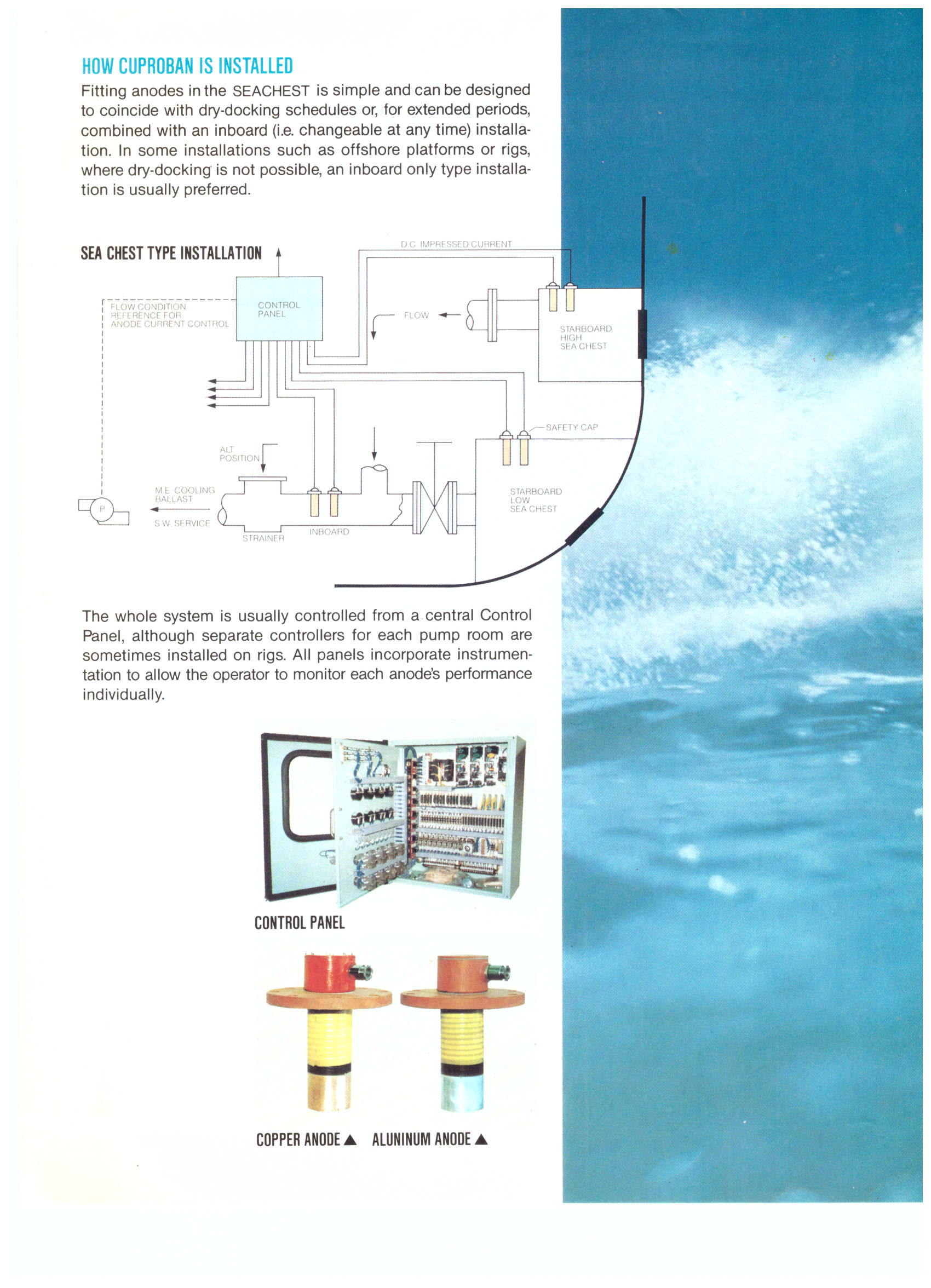
Technical Library
Barry Kirk — Design & Innovation Archive
Original technical documents, patents, and published papers by Barry Kirk — the designer of the Cuproban electrolytic MGPS system and the Anode Saving Device. These documents establish the provenance and technical heritage of the Cuproban system.
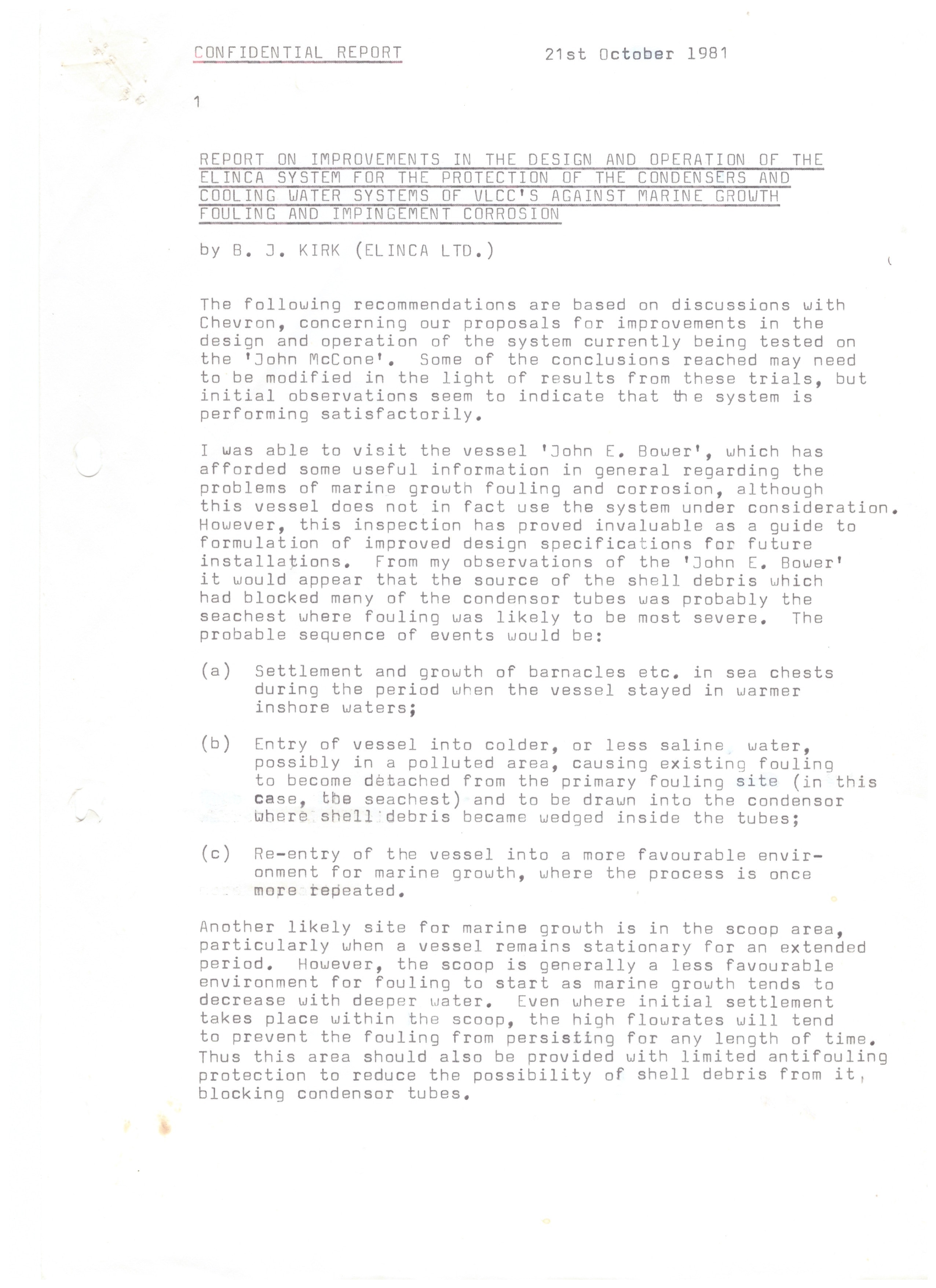
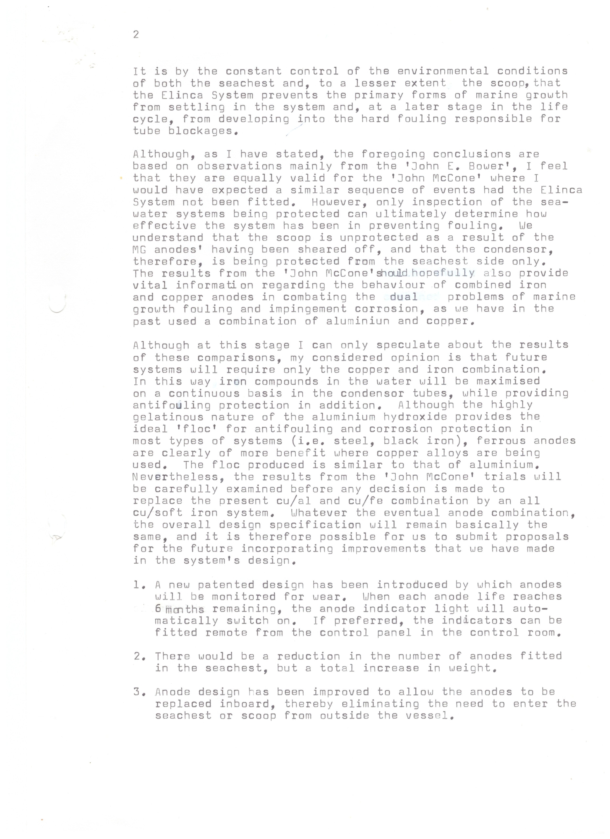
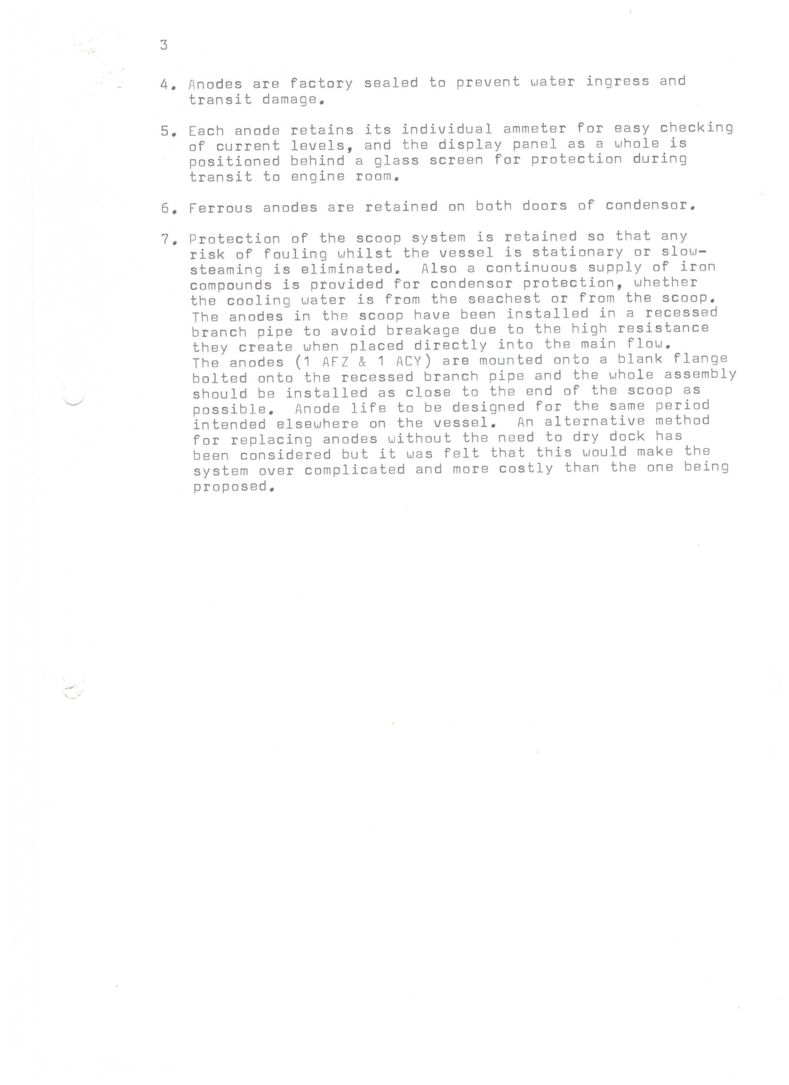
Confidential Technical Report · Elinca Ltd · 21 October 1981
Elinca System — Improvements in Design and Operation (VLCC Condensers & Cooling Water Systems)
The earliest document in the Cuproban archive. Confidential report by B. J. Kirk, Managing Director – Technical, Elinca Ltd, dated 21 October 1981 — seven months before the OTC Conference Paper (May 1982). Based on discussions with Chevron regarding the system under trial on the VLCC 'John McCone', and observations from inspection of the VLCC 'John E. Bower'. Sets out seven design improvements including: (1) a new patented anode wear monitoring system with 6-month indicator; (2) inboard anode replacement eliminating the need to enter the sea chest from outside the vessel; (3) factory-sealed anodes; (4) individual ammeters per anode; (5) ferrous anodes retained on both condenser doors; and (6) scoop protection via recessed branch pipe. Contains Barry Kirk's earliest written statement that future systems will require only the copper and iron (soft iron) anode combination — the foundational technical judgement behind the Cuproban system. Page 4 not yet located; will be added when found.

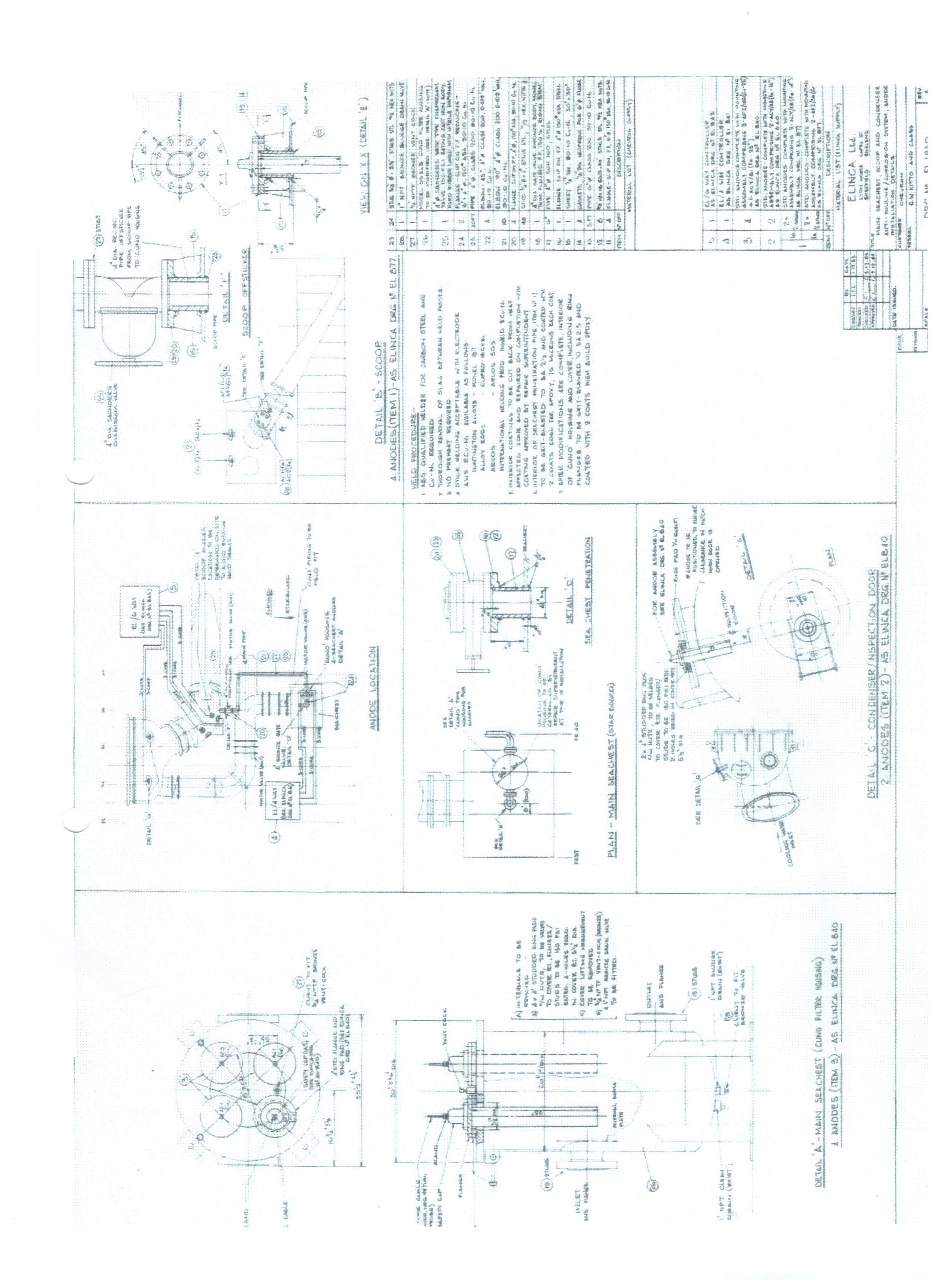
Engineering Drawing · Elinca Ltd · VLCC Installation
Elinca Ltd — VLCC Seachest Anode Installation Drawing (VLCC Kitto)
Elinca Ltd engineering drawing showing the seachest anode installation arrangement for a VLCC, believed to relate to the VLCC Kitto. The drawing details the Main Seachest (Clang Filter Housing), Condenser/Inspection Door, and Scoop configurations — with anode positions (Items 1, 2 and 3) referencing Elinca drawings EL.B40 and EL.677. This installation design is consistent with the improvements described in the Elinca Confidential Report of 21 October 1981, which was itself based on the positive results of the Elinca system trial aboard the VLCC John McCone operated by Chevron. The drawing documents the engineered solution that followed that trial — including inboard anode replacement, recessed scoop branch pipe, and the copper/iron anode combination that became the foundation of the Cuproban system.
Patent Specification
UK Patent Application GB2118972A
Original published specification for the Anode Wear System device designed by Barry Kirk. Covers the stainless steel probe, resistance circuit, relay mechanism, and alarm system.
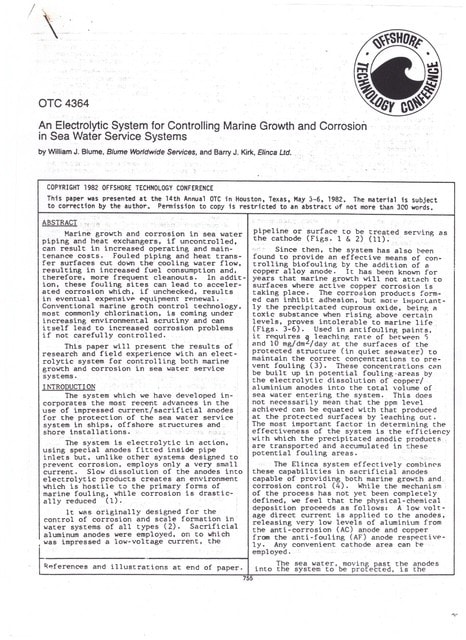
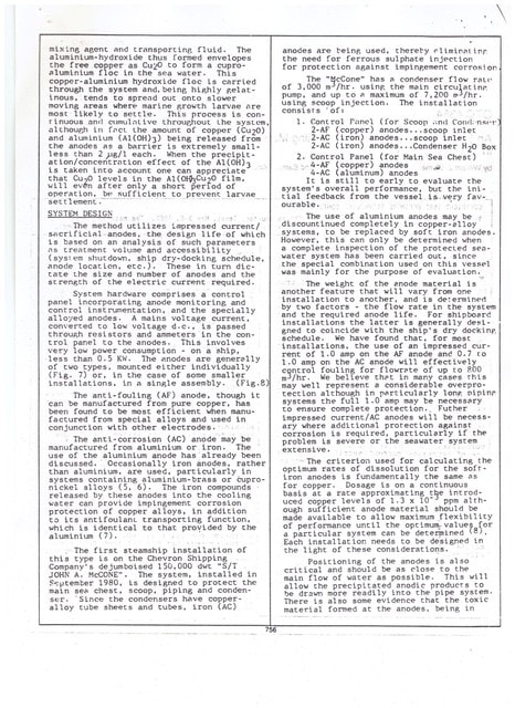
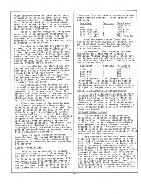
Conference Paper · OTC No. 4364 · 1982
An Electrolytic System for Controlling Marine Growth and Corrosion in Sea Water Service Systems
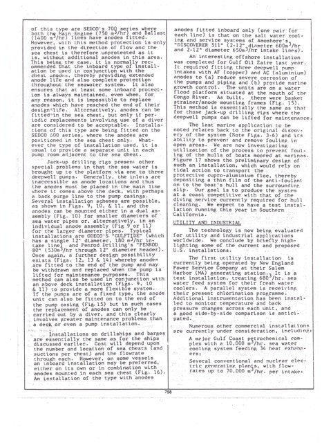
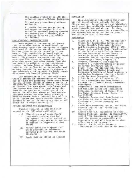
William J. Blume & Barry J. Kirk, Elinca Ltd. Presented at the 14th Annual Offshore Technology Conference, Houston, Texas, 3–6 May 1982. Documents the early development and field application of electrolytic MGPS technology on offshore drilling rigs including Sedco installations, marine vessels, and utility applications. Click any page to view full size.
Installation Records · 1983
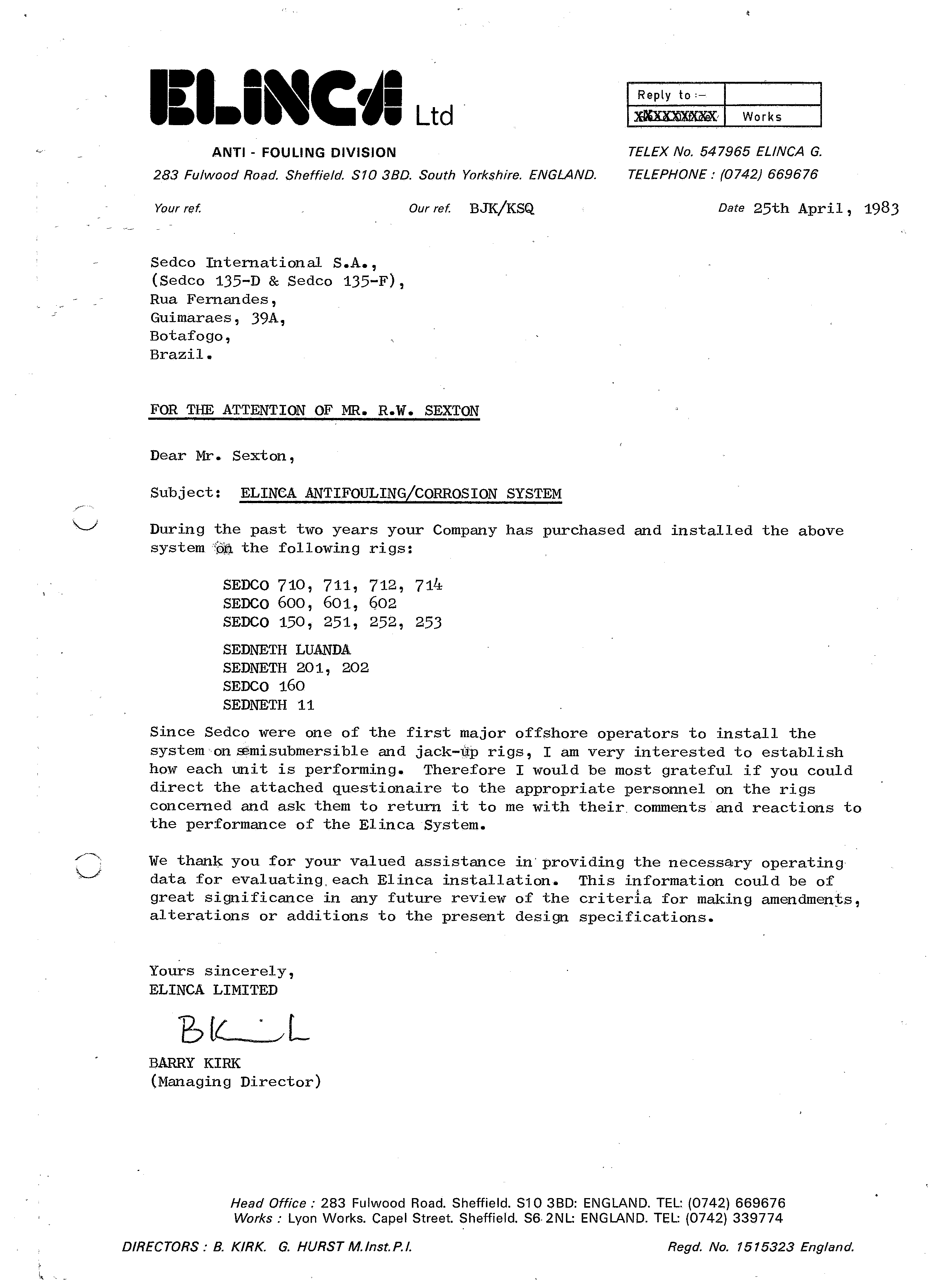
Sedco Rig Installation Correspondence
Signed letter from Barry J. Kirk, Managing Director of Elinca Ltd, to Sedco International S.A., dated 25 April 1983. Lists all Sedco drilling rigs fitted with the Elinca electrolytic antifouling and corrosion control system — including Sedco 710, 711, 712, 714, 600, 601, 602, 150, 251, 252, 253, Sedneth Luanda, Sedneth 201, 202, Sedco 160, and Sedneth 11. Sedco were among the first major offshore operators to install the system on semisubmersible and jack-up rigs.
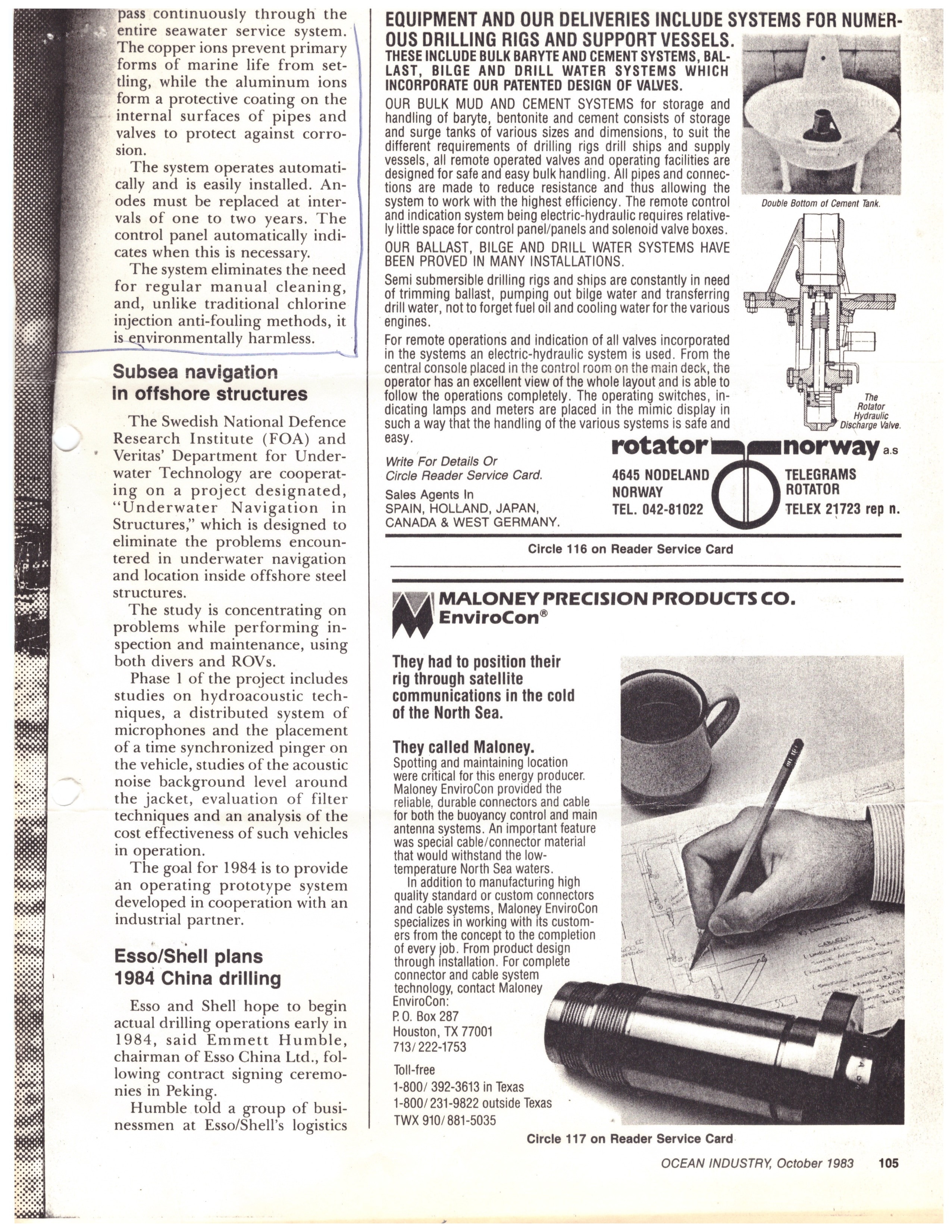
Trade Press · Ocean Industry · October 1983 · pp.103–105
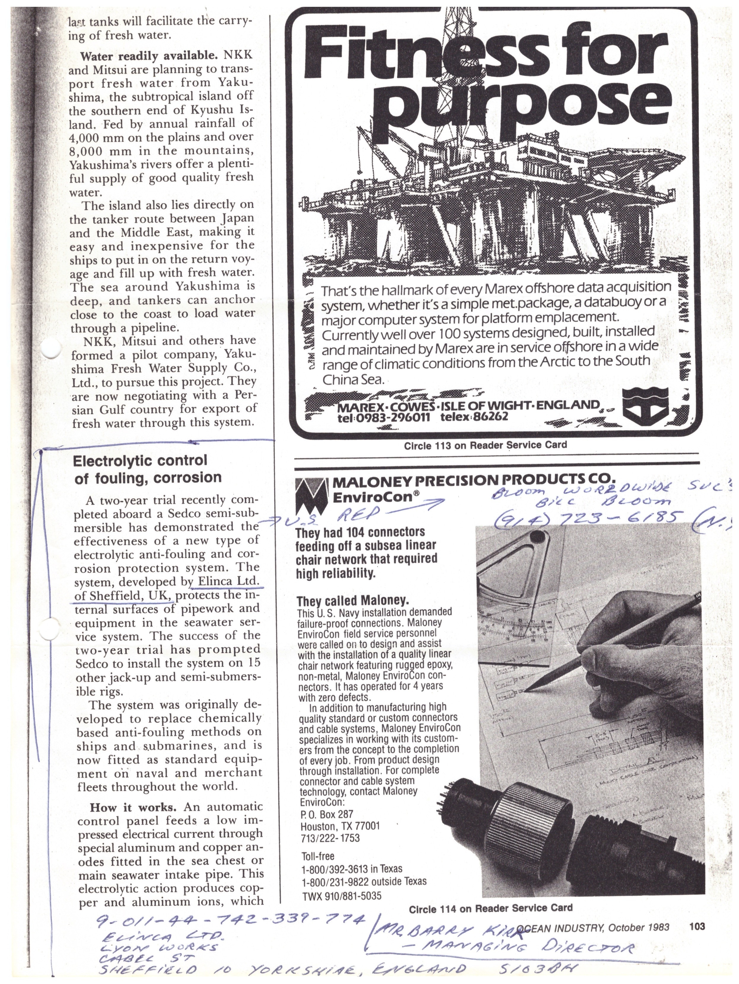
Electrolytic Control of Fouling, Corrosion — Ocean Industry, October 1983
Independent editorial coverage in Ocean Industry — the leading US offshore industry trade journal — October 1983. The article reports that a two-year trial aboard a Sedco semi-submersible had demonstrated the effectiveness of the Elinca electrolytic anti-fouling and corrosion protection system, developed by Elinca Ltd. of Sheffield, UK. The success of the trial prompted Sedco to install the system on 15 further jack-up and semi-submersible rigs. The article describes the operating principle — aluminium and copper anodes in the sea chest or main seawater intake pipe, automatic control panel, anode replacement intervals of one to two years — and notes the system had been fitted as standard equipment on naval and merchant fleets worldwide. Barry Kirk's own working copy, with his handwritten contact details and title (Managing Director, Elinca Ltd., Lyon Works, Cabel Street, Sheffield S10 3AH) annotated in the margin.

System Overview · Cuproban Systems
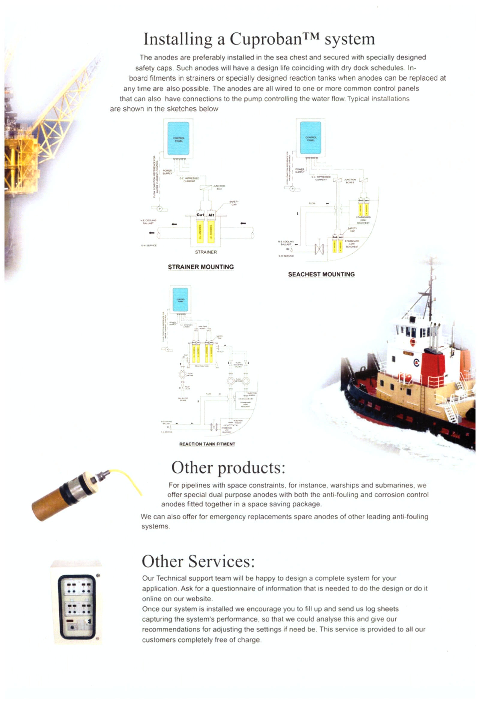
Cuproban™ System — Installation Diagrams & Technical Overview
Two-page technical overview of the Cuproban™ electrolytic anti-fouling and corrosion control system. Page 1 describes the problem of marine fouling, system features including the Anode-Wear and Anode-Save functions, and the operating principle. Page 2 shows the three standard installation configurations — Strainer Mounting, Seachest Mounting, and Reaction Tank Fitment — with schematic diagrams. These documents also reference the original Elinca Ltd inboard installation method (Fig. 14 Jack-Up Rig; Fig. 15 Gulf Zaire water-flood platform) developed by Barry Kirk prior to the founding of Cuproban Systems Ltd in 1984.
Installation note: Anodes are not fitted directly in-pipe. All three configurations shown — Strainer Mounting, Seachest Mounting, and Reaction Tank Fitment — position anodes correctly to avoid excessive turbulence in the seawater flow. Direct in-pipe anode mounting is not recommended practice.
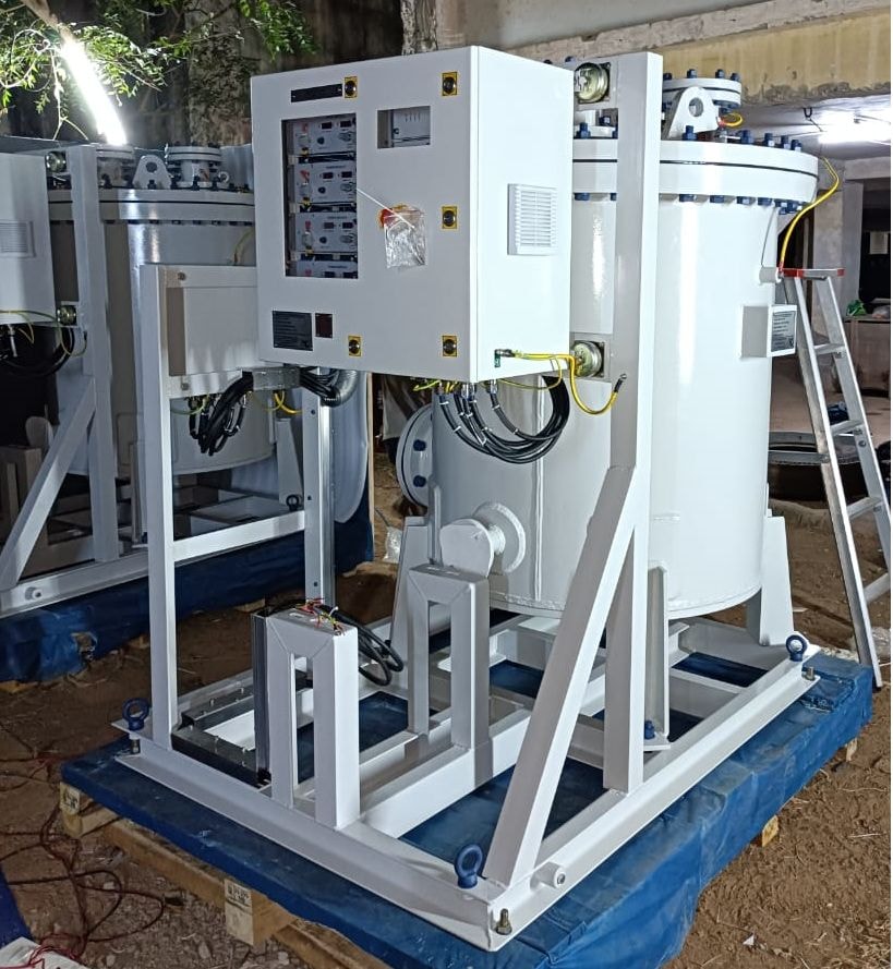
Installation Photo · Treatment Tank MGPS · FPSO Era
Treatment Tank MGPS — Modern FPSO Installation
Photograph of a Treatment Tank MGPS unit as installed on FPSO Bacalhau. This represents the mature form of Barry Kirk's MGPS technology — a dedicated seawater treatment tank fitted with copper and aluminium anodes, superseding the earlier caisson-based inboard method developed during the Elinca era (see Fig. 14 & 15 above). The Treatment Tank configuration was developed by Cuproban Systems Ltd during the Jotun partnership period (1987–2004) and remains the standard approach for large FPSOs and offshore production vessels.
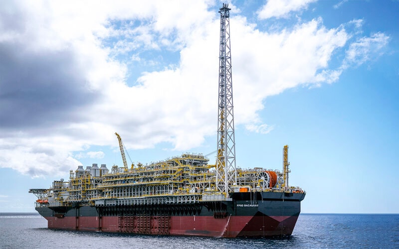
Vessel Photo · FPSO Bacalhau · Treatment Tank MGPS
FPSO Bacalhau — Cuproban MGPS Installation
FPSO Bacalhau, one of the modern floating production, storage and offloading vessels fitted with a Cuproban Treatment Tank MGPS system. The vessel confirms the continued deployment of Barry Kirk's original MGPS design concept on large-scale offshore production assets. The Treatment Tank MGPS units on vessels of this class were manufactured during the period when Sargam Metals Plc held the Cuproban manufacturing licence (2006–2013). Sargam Metals Plc is now dormant. Sargam Cathodic Protection, a separate entity, was not formed until 2019 and has never held a licence from Cuproban Systems Ltd. CUPROBAN® is a registered trademark of Barry John Kirk (UK No. 2238001 · EU No. 002917730); no licence is currently in force.
Installation Record · 1984–2004 · Cuproban / Jotun Partnership
Worldwide Vessel & Operator Installations — Cuproban MGPS/SAFE Technology
From 1984, Cuproban MGPS/SAFE technology was supplied to shipyards, operators, and owners of cruise ships, merchant vessels, ferries, drilling rigs, and offshore platforms worldwide. The following operators and yards received Cuproban systems during the partnership period with Jotun (1987–2004) and the wider Cuproban trading period from founding in 1984. Over 300 systems were installed worldwide.
This record establishes the commercial scale and international reach of Cuproban MGPS/SAFE technology during the period 1984–2004. All systems were designed by Barry Kirk and supplied under the CUPROBAN® trademark. CUPROBAN® is a registered trademark of Barry John Kirk (UK No. 2238001 · EU No. 002917730).
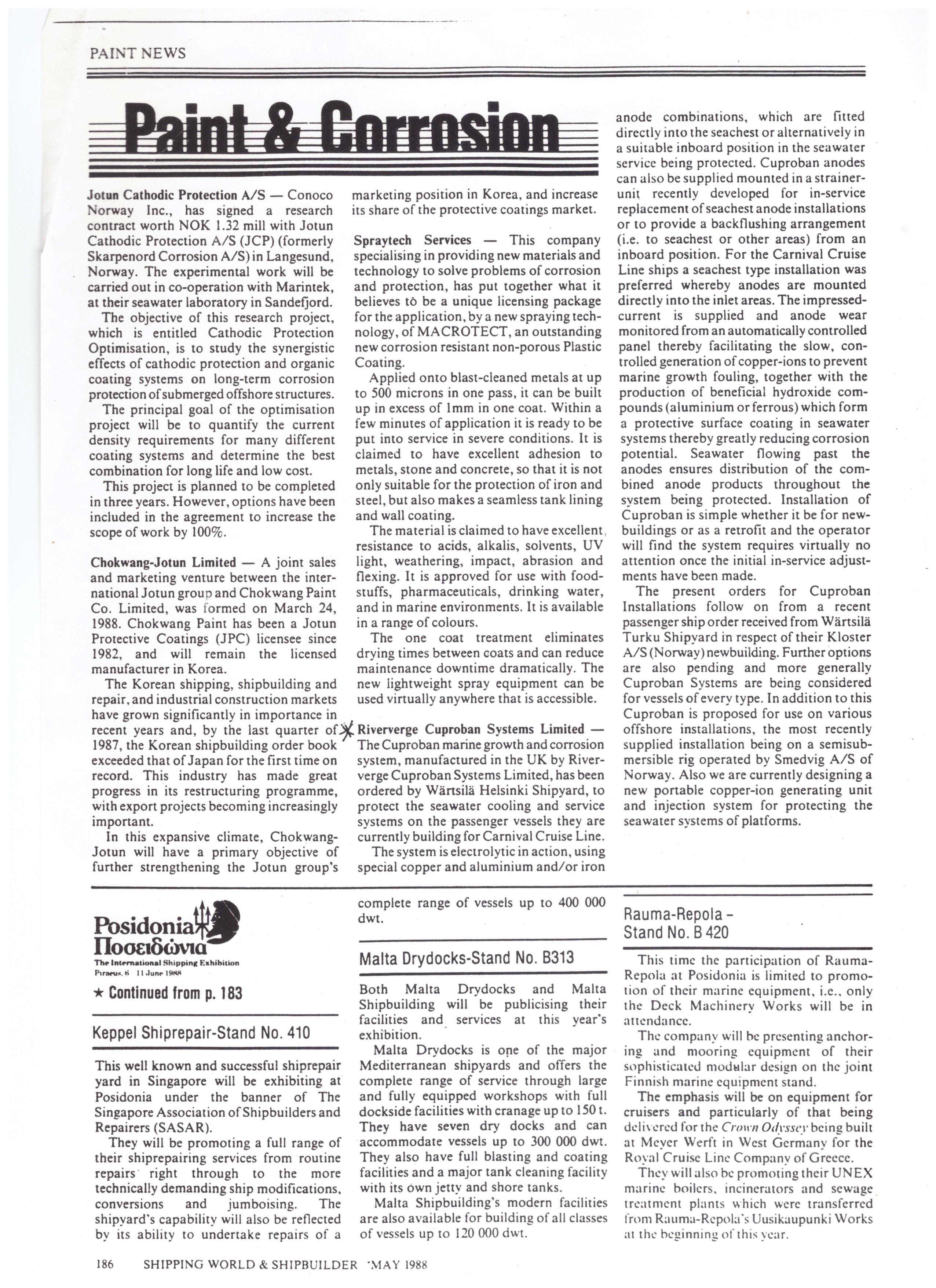
Shipping World & Shipbuilder · Paint & Corrosion · May 1988 · p.186
Trade Press — Riververge Cuproban Systems Limited
Industry article published in Shipping World & Shipbuilder, May 1988 (page 186), under the Paint & Corrosion section. Confirms that the Cuproban MGPS, manufactured in the UK by Riververge Cuproban Systems Limited, had been ordered by Wärtsilä Helsinki Shipyard to protect the seawater cooling and service systems on passenger vessels being built for Carnival Cruise Line. Also references a further order from Wärtsilä Turku Shipyard for a Kloster A/S (Norway) newbuilding, and confirms the most recently supplied offshore installation on a semisubmersible rig operated by Smedvig A/S of Norway. Notes development of a new portable copper-ion generating unit for platform seawater systems. Published during the Riververge acquisition period, prior to the formal Jotun partnership, with the CUPROBAN® trademark in place.
View Document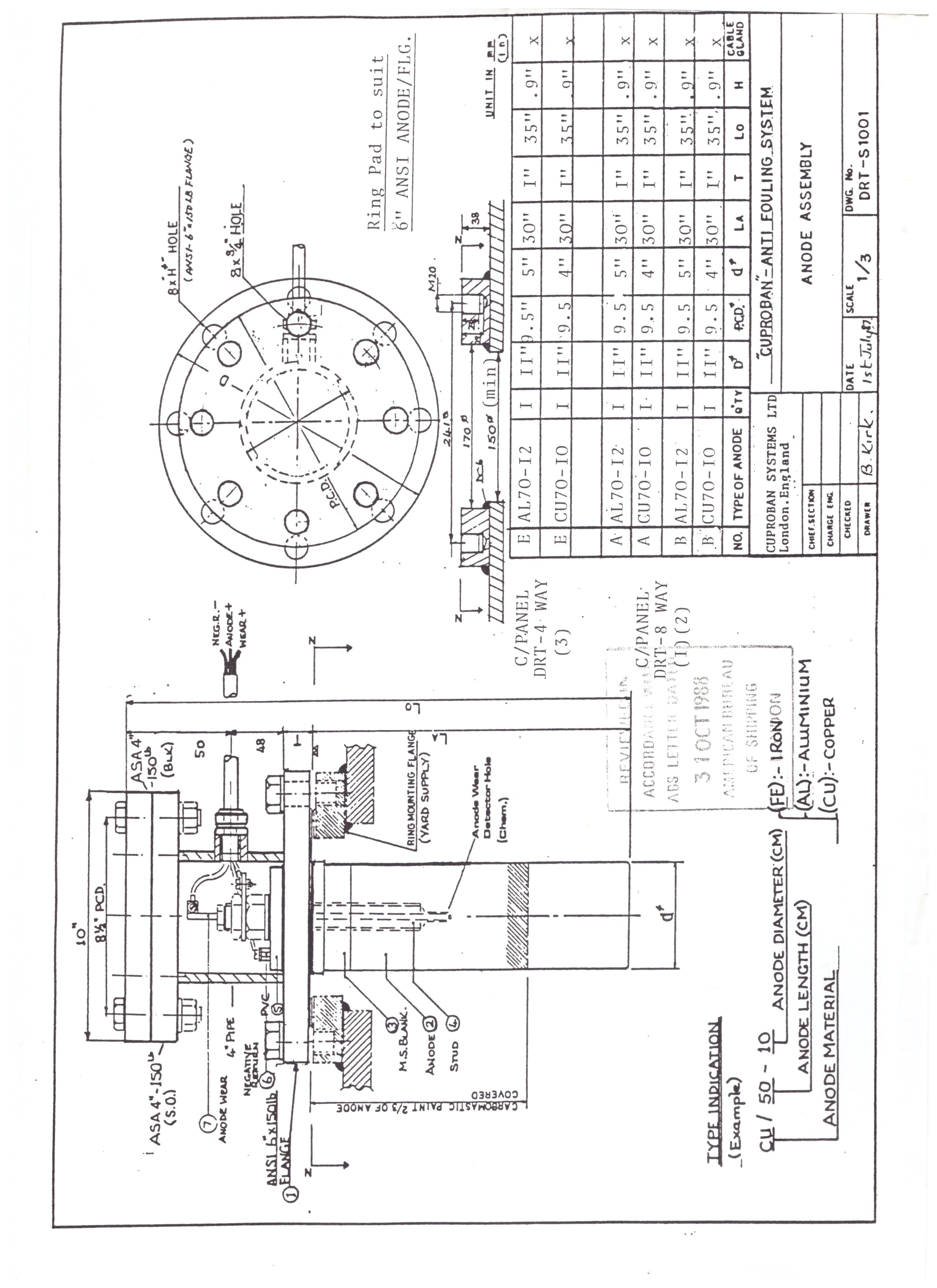
Engineering Drawing · DRT-S1001 · Anode Saving Device · ABS Stamped 1988
Anode Saving Device — Assembly Drawing DRT-S1001
Formal engineering drawing No. DRT-S1001, drawn by B. Kirk, Cuproban Systems Ltd, London. Shows the certified anode assembly incorporating the Anode Saving Device — Barry Kirk's original innovation for detecting anode wear before the anode is fully consumed. A stainless steel probe, insulated by a sleeve, is set just below the anode bolt; when the anode wears to the probe tip, a relay shuts down operating current and triggers a visual and audible alarm on the control panel. Covers iron (FE), aluminium (AL), and copper (CU) anode configurations for a 6-inch ANSI flange. Stamped by the American Bureau of Shipping, 3 October 1988. The underlying invention is published as UK Patent Application GB2118972A, available to download above.
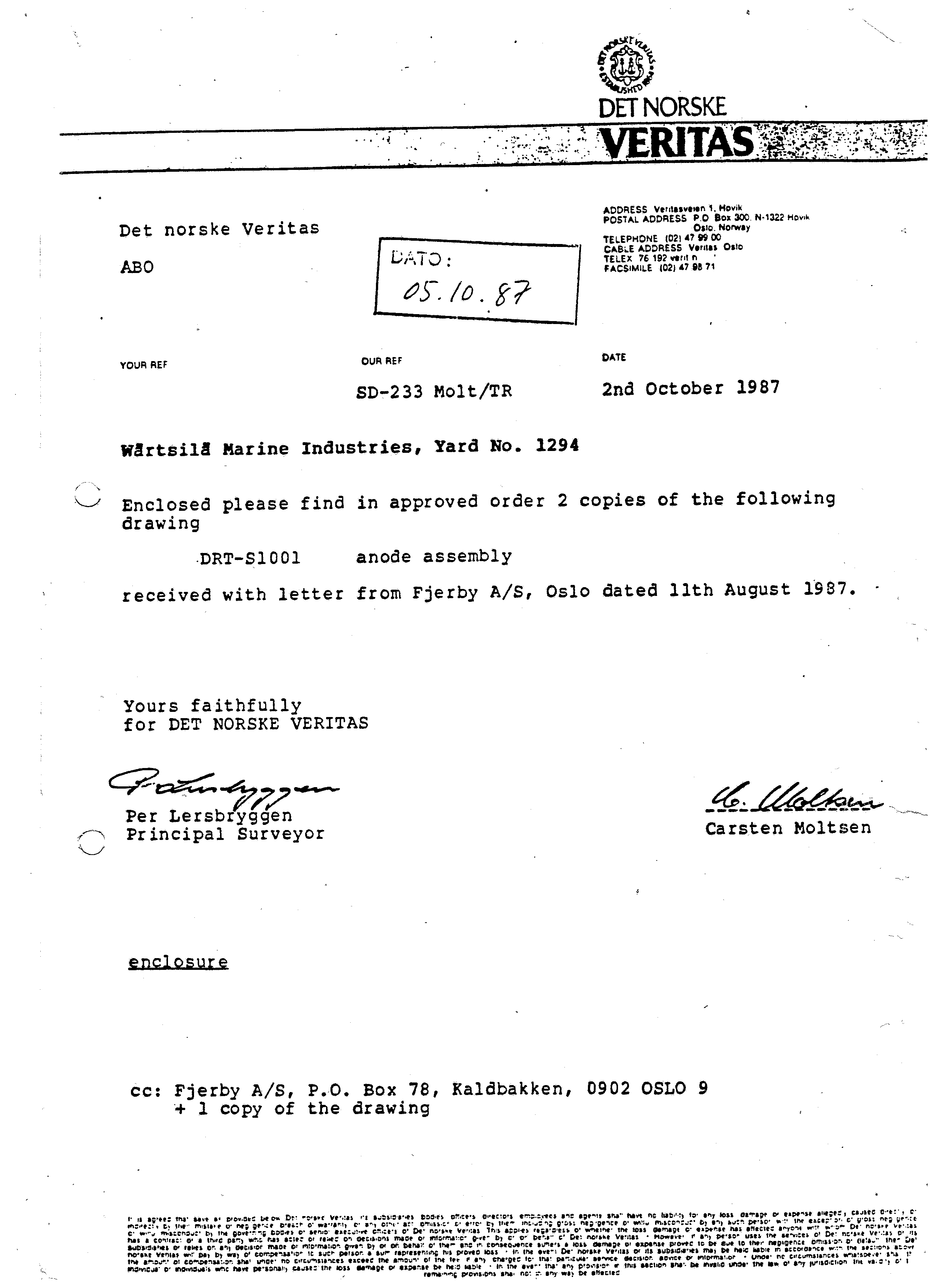
Type Approval · Det Norske Veritas · 2 October 1987
DNV Approval — Anode Assembly Drawing DRT-S1001
Letter from Det Norske Veritas (ref. SD-233 Molt/TR), Oslo, dated 2nd October 1987, returning two approved copies of Drawing DRT-S1001 — the Cuproban anode assembly — for use on Wärtsilä Marine Industries, Yard No. 1294. Signed by Per Lersbryggen (Principal Surveyor) and Carsten Moltsen. The drawing was submitted via Fjerby A/S, Oslo. Wärtsilä Yard No. 1294 relates to the construction of a Carnival Cruise Lines vessel during this period. This letter establishes formal classification society approval of the Cuproban anode assembly design by one of the world's leading marine classification bodies, confirming the system's fitness for installation on a major cruise vessel newbuild.
View DocumentResponse Template · Cuproban Systems Ltd · August 2026
RFQ Response Template — Spares & Service Enquiries (incl. Trademark Notice)
Standard starting-point template for responding to Spares & Service RFQs. Includes a factual trademark notice paragraph identifying Cuproban Systems Ltd as the sole authorised source, noting that no licence is currently in force with any third party — including Sargam Cathodic Protection or any entity trading as Cuproban Systems Singapore — and that supply or servicing under those names has not been authorised. Also includes a technical checklist for confirming anode specification before quoting. Adapt per vessel as required; the trademark paragraph should appear in all responses where the enquirer may have previously dealt with an unlicensed supplier.
Letter Template · Cuproban Systems Ltd · August 2026
Cease and Desist — Unauthorised Use of Cuproban® Trademark
Template cease and desist letter for use against parties using the Cuproban® trademark without a current licence from Cuproban Systems Ltd. Adapt the addressee, jurisdiction references, and specific particulars as required. Legal advice should be obtained before sending. Priority targets: Sargam Cathodic Protection (India) and any entity trading as Cuproban Systems Singapore or operating www.cuproban.com.
Letter Template · Cuproban Systems Ltd · August 2026
Vessel Operator Notice — Trademark & Authorised Supply (e.g. Serco Defence / SD Fortress)
Template letter for use with vessel operators who have an existing Cuproban MGPS installation and may have been approached by, or have previously sourced spares from, an unlicensed third party. Adapt the vessel name, operator, and specific details as required. Tone is professional and informative — not adversarial. The objective is to establish direct contact, confirm your position as trademark holder, and offer genuine support going forward.
Submit a Document
Upload Technical Documents
Use this form to submit the OTC Paper 1982, Sedco rig installation lists, anode drawings, or any other technical documents for the Cuproban archive. Files are received securely and stored privately. Accepted formats: PDF, JPG, PNG, TIFF — up to 20 MB per file.
Design Provenance
Soft Iron Anode Development History
The use of soft iron anodes in electrolytic MGPS systems to protect copper-nickel seawater pipework against impingement corrosion is original Cuproban development work, conceived and implemented by Barry Kirk in the early 1980s. Critically, the combined use of copper and soft iron anodes together in a single MGPS installation — as distinct from their independent prior use — is believed to have been first documented and applied by Barry Kirk, with the VLCC John McCone trial and the associated Elinca Confidential Report of October 1981 representing the earliest known record of this combined approach. This section sets out the documented history of that development and its relationship to subsequent commercial suppliers.
Origin — Early 1980s
Iron (Fe) anodes and copper (Cu) anodes had each been used independently in marine applications prior to the early 1980s. Barry Kirk identified that copper-nickel (CuNi) seawater pipework on offshore drilling rigs and vessels was susceptible to impingement corrosion — accelerated attack at bends, welds, and fittings caused by turbulent seawater flow — and that the standard copper and aluminium anode configuration used for biofouling control did not address this specific mechanism.
Kirk developed the combined use of soft iron and copper anodes together within a single MGPS installation. The soft iron anodes generate ferrous ions in the seawater flow, depositing a thin protective ferrous hydroxide film on the internal bore of CuNi pipework and substantially reducing impingement corrosion rates. To the best of current knowledge, this combined Cu/Fe anode configuration in a single MGPS system was first applied and documented by Barry Kirk at Elinca Ltd.
The earliest documentary evidence is the Elinca Confidential Report dated 21 October 1981 — sent to Chevron in connection with the system then under trial on the VLCC John McCone — together with the associated VLCC Kitto installation drawing from the same period. Both documents are held in the Cuproban archive. Further records relating to this trial period are being sought. This combined approach was carried forward into Cuproban Systems Ltd from its founding in 1984.
Inboard Strainer Method
For offshore platforms and drilling rigs where sea chest access is not available, Kirk developed the inboard strainer method: soft iron anodes are fitted inside a strainer in the seawater system, inboard of the sea chest, and connected to the MGPS control panel. This allows the ferrous ion dosing to be applied without dry-docking and without modification to the sea chest itself.
The inboard strainer configuration was field-proven on Sedco semisubmersible and jack-up drilling rigs from 1981 onwards, as documented in the Sedco installation correspondence of April 1983 and in the OTC Paper 1982 presented at the Offshore Technology Conference, Houston. The installation diagrams for the Gulf Zaire water-flood platform (Fig. 15) in the Technical Library above show this method as implemented by Elinca Ltd.
Relationship to Subsequent Commercial Suppliers
The use of soft iron anodes in electrolytic MGPS systems — including their application in inboard strainer configurations for CuNi pipework protection — has subsequently been adopted and marketed by other commercial suppliers of MGPS equipment. These suppliers entered the market after the Elinca and Cuproban installations were already in service.
Cuproban Systems Ltd does not assert that any current supplier has acted improperly in offering soft iron anode products. The Elinca patent lapsed and the underlying technical principle is not proprietary. However, the documented record — the OTC Paper 1982, the Sedco correspondence 1983, the Elinca installation diagrams, and the Cuproban engineering drawings — establishes clearly that this method was conceived, developed, and field-proven by Barry Kirk prior to the existence of any current commercial competitor offering equivalent products.
This provenance record is published here as part of Cuproban's commitment to accurate technical history. Any party wishing to licence the Cuproban trademark or to engage with Cuproban Systems Ltd on the basis of this heritage is invited to make contact.
Design Origin Notice
The soft iron anode method for CuNi impingement corrosion protection, and its application in inboard strainer configurations, was developed by Barry John Kirk at Elinca Ltd and Cuproban Systems Ltd. Supporting documentation is available in the Technical Library above. Enquiries regarding licensing or technical heritage should be directed to [email protected].
Design Provenance
Original Cuproban Designs
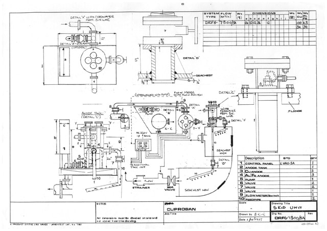
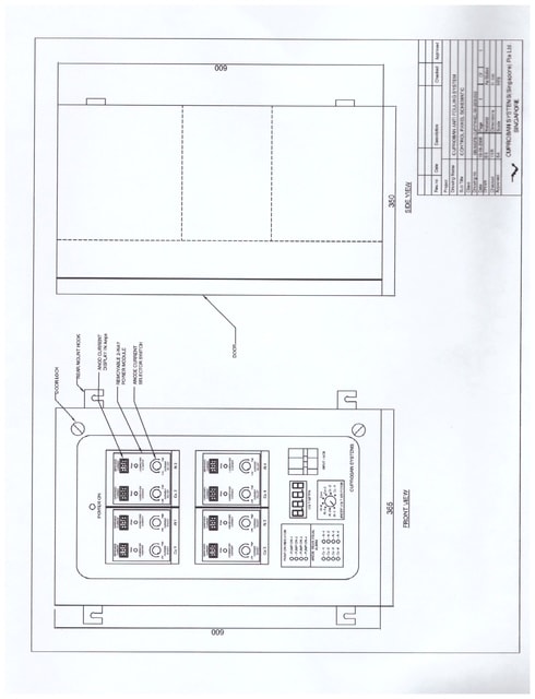
The drawings below are original Cuproban system designs by Barry Kirk, derived directly from the Elinca patent developed prior to the founding of Cuproban Systems Ltd in 1984. They establish the design lineage of Cuproban MGPS technology and confirm that the engineering principles now in use — including by other companies — originate from Barry Kirk's work.
The original Elinca patent lapsed when the company's manufacturing base closed. However, the designs, drawings, and technical specifications remain the intellectual property of Cuproban Systems Ltd. Their publication here forms part of the documented record of design origin.
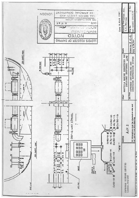
Original Design Drawing — Sheet 1
Barry Kirk — Cuproban Systems Ltd
Original Design Drawing — Sheet 2
Barry Kirk — Cuproban Systems Ltd
Original Design Drawing — Sheet 3
Barry Kirk — Cuproban Systems Ltd
Design Ownership Notice: All Cuproban system designs and drawings are the original work of Barry John Kirk and the intellectual property of Cuproban Systems Ltd. Any reproduction, manufacture, or use of these designs without a current written licence from Cuproban Systems Ltd is unauthorised.
Discuss your installation requirements
Our UK engineering team will advise on the right Cuproban system for your vessel, platform, or facility.